


Dental Implant Drill Compatibility: Geometry, Osteotomy Sequence & Fixture Design
A dental implant drill—often called a stepped drill, osteotomy drill, or final form drill—is not a generic twist bit. It is an instrument engineered to create a precise osteotomy that accepts a specific implant’s geometry, depth and surgical protocol. Achieving compatibility is a multi‑layered challenge: the drill must reproduce the implant’s macro‑shape incrementally, clear bone debris, avoid overheating, and adapt to variable bone quality without deviating from the implant manufacturer’s intended fit. Below, we unpack these factors in a structured way.
1. The Starting Point: Implant Macro‑Design Dictates Drill Geometry
The drill sequence is a physical mirror of the implant body. Two broad implant categories illustrate this:
-
Parallel‑walled implants require a cylindrical osteotomy. The final drill, typically a straight parallel drill, matches the implant’s core diameter. A bone tap may then cut the thread groove if the implant is not self‑tapping.
-
Tapered implants need a tapered osteotomy. A tapered final drill, or a stepped drill with a pronounced taper, ensures the implant can seat fully without excessive apical compression. Mismatch here leads to either binding at the crest or a loose apex.
Beyond body shape, the implant collar height matters. Bone‑level implants and tissue‑level implants have different vertical reference points; drills must carry depth marks or stop collars calibrated to the intended implant length from the respective reference. This is why drills within a system are often labeled with specific implant line names—their stops are set for that platform.
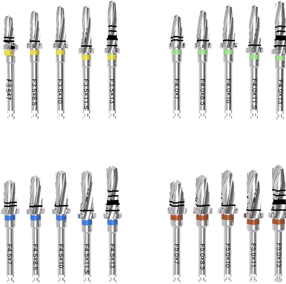
2. The Stepped Sequence: Gradual Diameter Increase Is Deliberate
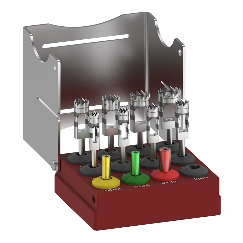
A set of drills does not jump from a pilot drill to the final diameter in one step. The sequence is stepped, progressively enlarging the osteotomy. This incremental approach serves three purposes:
-
Bone preservation – A sudden large diameter jump could generate excessive torque, heat, and micro‑fractures.
-
Directional control – Each successive drill follows the initial pilot path, reducing the risk of wobble or axis deviation.
-
“Reserved space” for the implant – The Final Drill diameter is not always the exact outer diameter of the implant. In dense bone, it may be very close; in soft bone, the protocol may call for under‑preparation (a slightly smaller final drill) to increase insertion torque and primary stability. This intentional undersizing is a critical part of drill–implant compatibility, balancing biological needs with mechanical fixation.
Depth is controlled along this sequence by physical stops, engraved lines, or a surgical guide. Every implant length (e.g., 8 mm, 10 mm, 12 mm) needs a drill of exactly the corresponding active length from the platform reference point.
3. Flute Design and Chip Evacuation: Not Optional
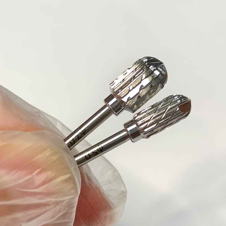
Every osteotomy drill carries helical flutes that function as debris channels. When these flutes are poorly designed or inadequate, bone chips pack into the flutes, increasing friction, temperature, and insertion torque. The result can be thermal necrosis of bone and unpredictable seating.
Flute geometry also influences cutting efficiency and chip transport:
-
A deep, polished flute clears chips rapidly and reduces clogging.
-
The helix angle affects how aggressively the drill cuts and how quickly chips exit.
-
Dull or blocked flutes force the clinician to apply more pressure, worsening heat and vibration.
From a manufacturing perspective, flute profile consistency is essential to maintain predictable cutting behavior across hundreds of drills.
4. Runout, Sharpness and Heat: The Precision Triad
Three manufacturing‑related factors directly affect the osteotomy quality:
-
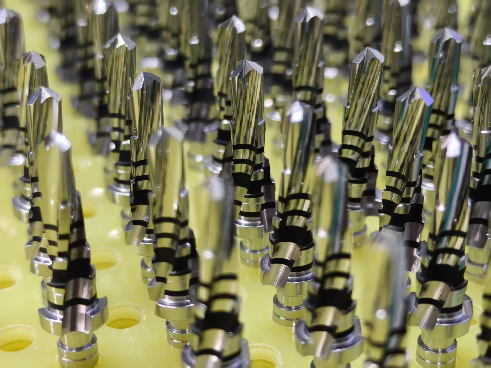
Drill runout (dynamic wobble) – If the drill tip does not rotate concentrically with the shank axis, it reams an oversized or oval osteotomy. This compromises primary stability and can lead to implant micromotion. Runout must be tightly controlled, especially for long drills and guided surgery applications.
-
Cutting edge sharpness – A sharp edge shears bone with minimal pressure, lowering heat. After repeated autoclave cycles and uses, even high‑grade stainless steel edges dull. The number of reliable uses before degradation matters to both clinicians and distributors.
-
Heat generation – Bone is irreversibly damaged above approximately 47°C for one minute. Heat comes from friction and cutting force. Adequate irrigation (external or through internal coolant channels in the drill), controlled RPM, and an efficient flute design all work to keep temperature down. The drill material’s thermal conductivity also plays a role.
5. Bone Quality Adaptation and the Role of Cortical Drills
Bone is not uniform. The implant site may present with a thick cortical crest (D1–D2 bone) or soft trabecular core (D3–D4). Drill protocols adjust accordingly, and this adaptation must be built into the system’s drill kit:
-
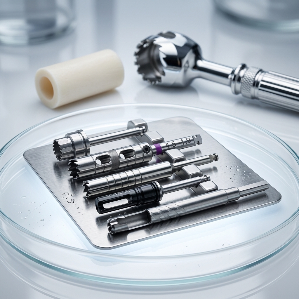
Cortical bone drill (cortical countersink drill) – Used to widen the crestal few millimeters of the osteotomy after final diameter preparation. This reduces the insertion stress on the implant at the cortical rim, lowering the risk of crestal bone fracture or excessive pressure necrosis, especially with self‑tapping tapered implants.
-
Osteotomes or bone condensers – In soft bone, some systems include instruments that condense bone laterally rather than cut it. The drill sequence then stops earlier, and the final shaping is done by condensing, not drilling.
-
Adjustable Final Drill sizes – Some implant systems offer a “dense bone drill” and a “soft bone drill” for the same implant diameter, differing by as little as 0.2–0.3 mm. This illustrates how tightly drill‑implant compatibility is tied to bone physiology.
6. Implant System Classification and Its Direct Link to Drill Design
The broad classification of dental implant systems shapes the entire drill armamentarium. Key distinctions include:
-
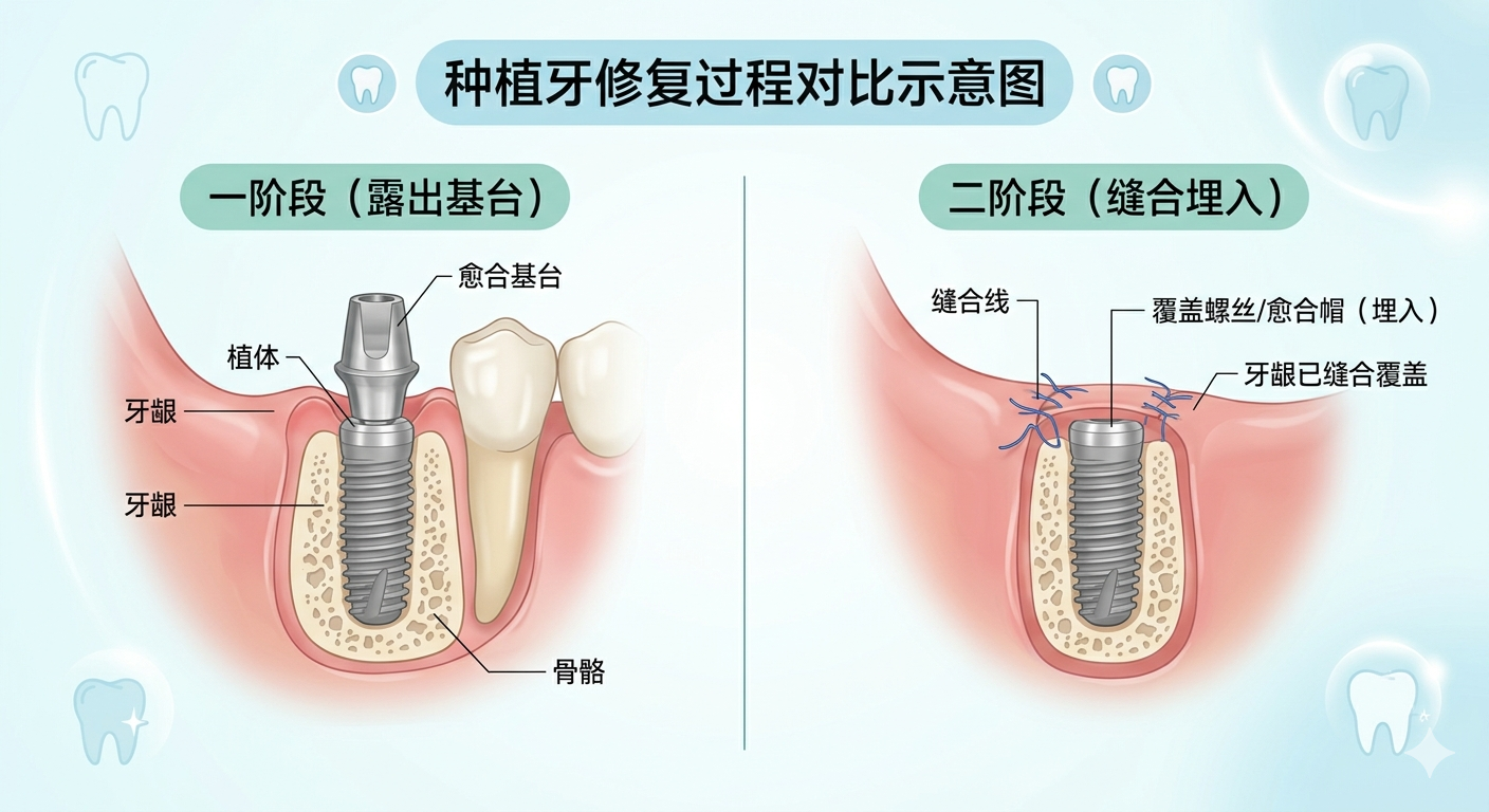
Tissue‑level vs. bone‑level – Tissue‑level implants have a smooth transmucosal collar; drills for these systems reference the soft‑tissue crest. Bone‑level drills reference the bone crest, and the surgical kit often includes a separate Profile Drill or countersink for the implant shoulder.
-
Self‑tapping vs. non‑self‑tapping – Self‑tapping implants can cut their own thread groove into the bone, so the osteotomy diameter is often slightly smaller, leaving bone to engage the threads. Non‑self‑tapping implants require a separate thread—forming tap, and the Final Drill diameter is typically closer to the implant core diameter.
-
Connection type (external hex, internal hex, conical connection) – While this does not directly change osteotomy shape, it influences the platform diameter and depth. For example, certain internal connection implants have a flared shoulder; the drill or countersink must create space for that geometry.
-
Surface treatment – Modern implants have moderately rough surfaces (e.g., SLA). The drill must produce an osteotomy wall smooth enough to allow implant insertion but not so polished that it eliminates friction. Surface roughness of the implant relies on mechanical interlocking, not a perfect mirror of the drill hole.
These classifications explain why a drill from System A may be dangerous to use with System B, even if the diameters appear similar. The taper angle, depth reference, apical shape and cortical engagement strategy are all tuned to a specific implant.
7. Additional Considerations from a Manufacturing and Clinical Perspective
Beyond the core design, several other factors contribute to true compatibility:
-
Surgical guide compatibility – In guided surgery, drills must pass through metal sleeves with tight tolerances. The drill’s shank diameter, length (including the extra length beyond the sleeve), and depth‑stop collar must match the guide system exactly. This often requires dedicated guided drill kits.
-
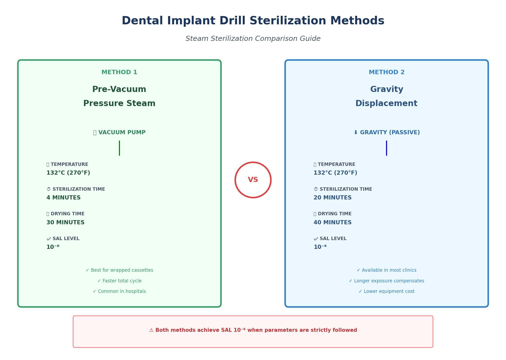
Single‑use vs. reusable – Repeated sterilization and use can alter drill dimensions through wear and corrosion, subtly changing diameter and cutting performance. Many protocols now limit the number of uses. A manufacturer’s claim about reuse life must be backed by validation data.
-
Marking durability – Depth marks that fade after a few autoclave cycles become a clinical risk. Laser‑etched, passivated markings must remain legible.
-
Material and coating – While the focus here is not on raw material selection, it is worth noting that the steel’s hardness, corrosion resistance and machinability directly influence edge retention and biocompatibility after wear.
8. Putting It All Together
Drill‑implant compatibility is not a single‑dimension problem. It starts with the implant’s shape and connection, extends through a carefully graduated sequence, integrates bone quality management, and requires manufacturing precision in runout, flute form and thermal behavior. For dental implant manufacturers and distributors evaluating drill partners, the most meaningful indicator is whether the engineering logic behind the drill kit aligns with the implant’s surgical philosophy.
As a manufacturer of osteotomy drills, we treat this compatibility as a functional specification—not as a marketing claim. Our approach is to reverse‑engineer nothing, but instead to design drills from the implant’s documented protocol requirements upward, verifying each parameter against calibrated test protocols. That is the only reliable way to ensure a drill set performs as intended.