


A Simple Guide to the Bone Ridge Split Kit
Understanding the ESSET Kit: Core Components and Design Philosophy
What Makes the ESSET Kit Different
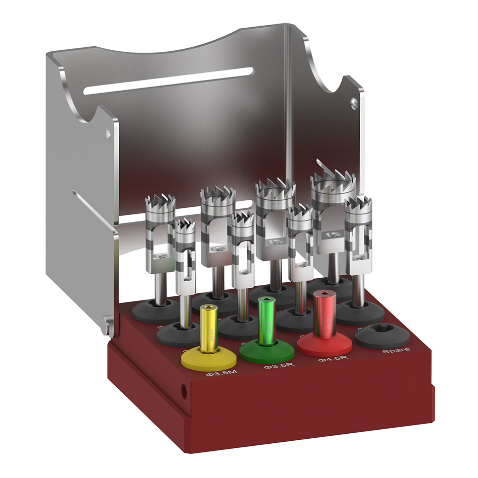
The Esset Kit is a comprehensive ridge split and bone expansion system designed specifically for narrow alveolar ridges. Its name—Easy Safe Stable Expanding and Tapping—reflects the core design philosophy: simplicity, safety, stability, and efficient bone expansion through a controlled drilling sequence.
The most distinctive feature of the Esset Kit is the elimination of chisels and mallets. Conventional ridge splitting techniques often require striking instruments that transmit mechanical impact forces to the patient’s skull, which many patients tolerate poorly. Reports in the literature describe postoperative complications including concussions and benign paroxysmal vertigo that may persist for several weeks. The Esset Kit completely avoids these issues by using motorized drills and a stepwise expansion sequence.
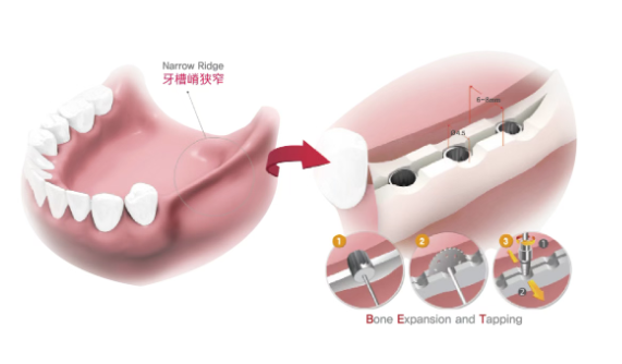
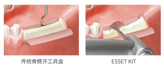
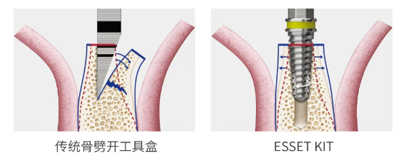
Key Components of the ESSET Kit
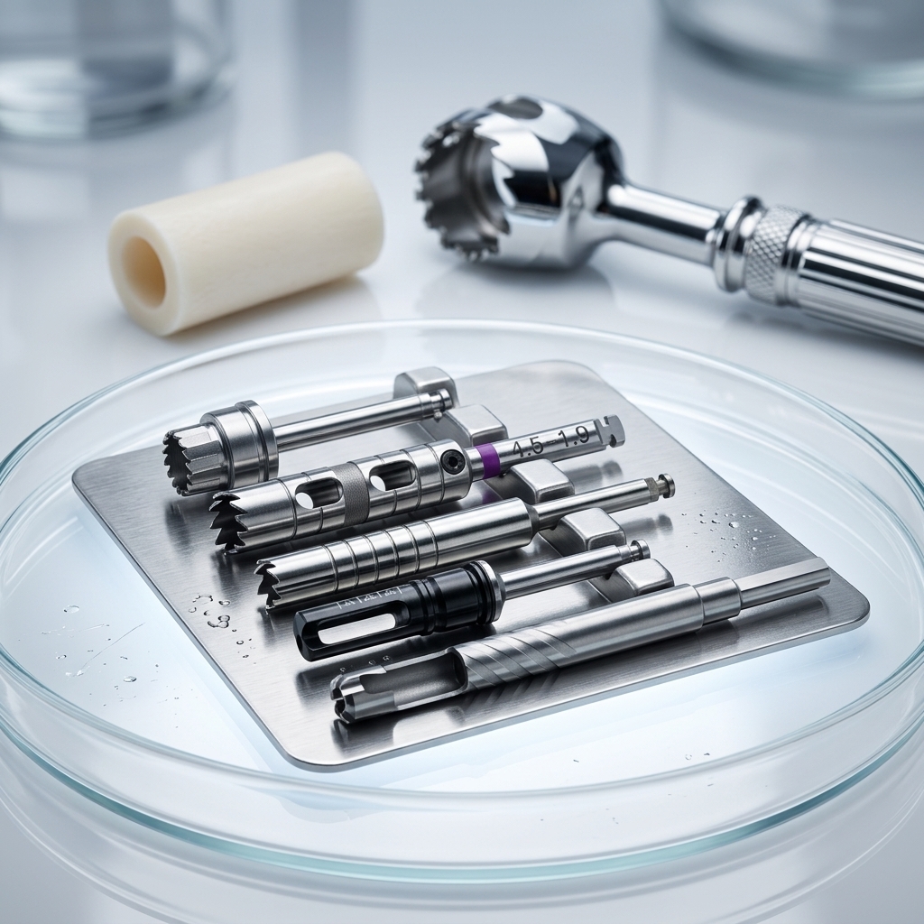
The Esset Kit contains the following essential instruments:
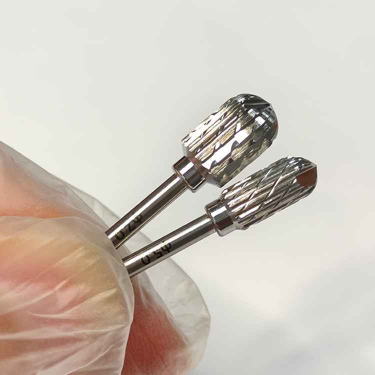
Crest Remover (7.0mm diameter): A roundshaped cuttingedge bur used to flatten the sharp alveolar ridge and create a stable bone plateau for subsequent drilling steps.
Initial Positioning Drill (Twist Drill): Used to mark and prepare the pilot hole at each intended implant site.
Bone Saws (7.0mm, 10.0mm, 13.0mm): Vertical and horizontal cutting instruments used to split the alveolar ridge along its full length.
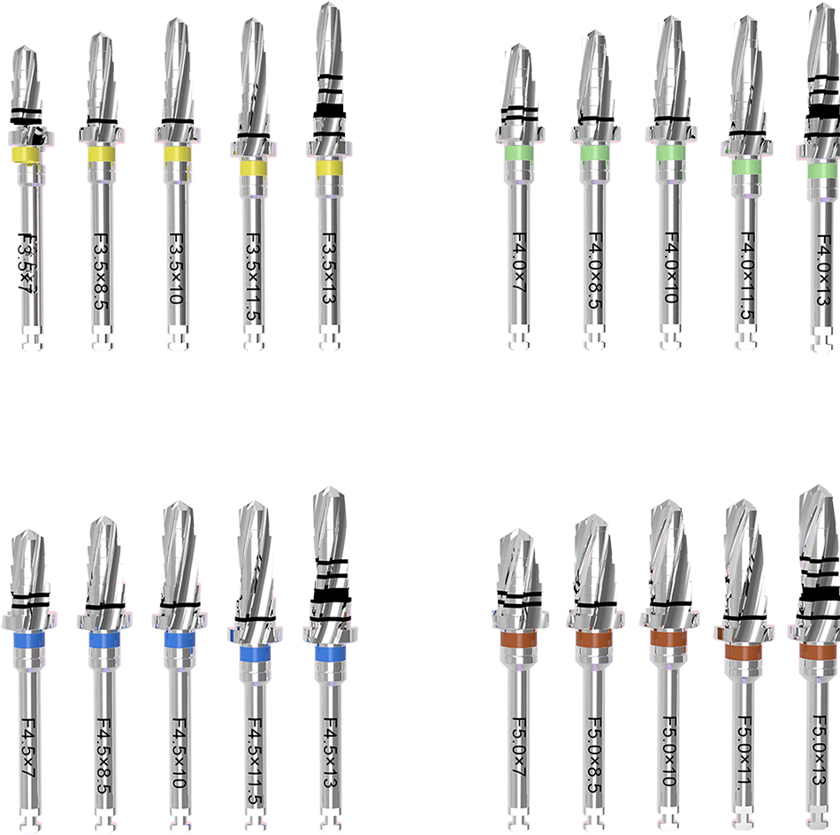
Expansion Drills (also known as forming drills or tapered expansion drills): Four sequentially sized tapered drills—1.6/2.8mm, 2.2/3.6mm, 2.7/4.1mm, and 3.1/4.5mm—that gradually expand the split bone through a selftapping motion, minimizing the risk of buccal plate fracture.
Mount Extension and torque wrench: Accessories for manual torque application when encountering high resistance.
The Science Behind the ESSET Technique
The ESSET technique leverages the viscoelastic properties of bone tissue. When the alveolar ridge is split and progressively expanded using the tapered expansion drills, the bone undergoes controlled deformation within its elastic limits. The expanded bone then attempts to return to its original shape, generating circumferential compression around the implant body. This elastic recoil produces exceptionally high primary stability, often comparable to or exceeding that achieved in native bone of adequate width.
Additionally, the technique creates a fourwall bony defect around the implant site. This configuration enhances blood supply from all directions simultaneously, promoting faster healing and potentially eliminating the need for additional bone graft or membrane.
Preoperative Assessment and Case Selection
Minimum Ridge Width Requirements
Before proceeding with the Esset Kit protocol, the clinician must confirm that the alveolar ridge meets the minimum width requirement. The horizontal ridge width at the crest must be at least 4.0mm. This can be assessed clinically using a periodontal probe under local anesthesia or radiographically using conebeam computed tomography (CBCT).
Indications for Ridge Split Technique
The ridge split technique is indicated for narrow edentulous ridges (width greater than 3.5mm but less than 5mm) where there is adequate vertical bone height but insufficient horizontal dimension to accommodate a standarddiameter implant. The technique works predictably in both the maxilla and mandible, though mandibular ridge splitting requires more careful case selection and surgical precision due to the dense cortical bone, which increases the risk of fracture.
Contraindications
The Esset Kit technique should not be used in cases of severely resorbed ridges with narrow basal bone width, active infection at the surgical site, uncontrolled systemic diseases that impair bone healing, or in patients with a history of radiation therapy to the head and neck region.
StepbyStep Surgical Protocol for the ESSET Kit
The following stepbystep protocol integrates the specific clinical parameters recommended by Osstem for the Esset Kit.
Step 1 – Crestal Bone Plateau Preparation with the Crest Remover
The first step in the ESSET sequence is to flatten the sharp, irregular alveolar ridge crest to create a stable, flat bone platform for subsequent drilling.
Select the 7.0mm Crest Remover and attach it to a surgical handpiece capable of delivering the recommended speed range. Set the handpiece speed to 1200–1500 RPM. Apply the crest remover to the alveolar ridge crest, moving horizontally across the planned implant sites to level the bone surface.
Critical note: The horizontal width of the alveolar ridge must be at least 4.0mm at this stage. For multiple missing teeth, use the crest remover to flatten each individual implant site separately. In the case of a threetooth edentulous span (e.g., teeth 35–37), the crest remover should be used to create three separate flattened platforms—one for each planned implant—to prepare for subsequent positioning, expansion, and implant placement steps.

Step 2 – Initial Drill Positioning
After flattening the crest, the next step is to mark the precise implant positions using the initial positioning drill (twist drill).
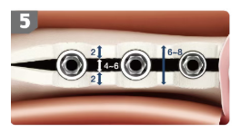
Determining implant positions for multiple edentulous sites: For a threetooth edentulous span such as teeth 35–37, the first implant site should be positioned 5.0mm distal to the mesial adjacent tooth, and the second implant site should be positioned 7.0mm distal to the first implant site. These distances ensure adequate interimplant spacing (typically 3.0–4.0mm between implants) and appropriate distance from adjacent natural teeth.
Set the handpiece speed to 1200–1500 RPM. Use the initial positioning drill to create pilot holes at each marked site to the desired depth.
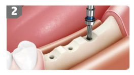
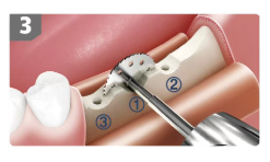
Step 3 – Vertical Ridge Splitting with the Bone Saw
Once the pilot holes are established, the alveolar ridge must be split along its full length to create a controlled fracture line that will allow lateral expansion.
Select the bone saw of appropriate length based on the required split depth. The Esset Kit includes three saw sizes: 7.0mm, 10.0mm, and 13.0mm. For most clinical situations, the 13.0mm saw is used to achieve fulllength splitting.
Vertical split technique: Insert the saw vertically into the bone at the prepared pilot hole and advance it to its full working length. The saw should split the ridge along the mesiodistal direction, creating a controlled osteotomy that separates the buccal and lingual cortical plates. The recommended speed for the bone saw is 1200–1500 RPM.
Special consideration for adjacent natural teeth: When working near a natural tooth, use the 7.0mm bone saw rather than the longer saws to minimize the risk of damaging the adjacent root structure.
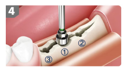
Step 4 – Horizontal Connection of Split Sites
After completing the vertical splits at each implant position, the next step is to connect these split sites horizontally.
Use the bone saw to create a horizontal cut along the mesiodistal direction, connecting the distal aspect of one split site to the mesial aspect of the adjacent split site. This horizontal connection transforms individual vertical osteotomies into a continuous split line, allowing the entire buccal cortical plate to be expanded as a single unit.
The recommended speed for this horizontal sawing step is also 1200–1500 RPM.
Step 5 – Sequential Bone Expansion with Forming Drills
This is the most critical step in the ESSET protocol. The split bone must be gradually expanded to create sufficient space for implant placement while preserving the integrity of the buccal cortical plate and leveraging bone elasticity for primary stability.
The Esset Kit includes four forming drills (tapered expansion drills) in sequentially increasing diameters:
Drill Size (mm) Function
1.6 / 2.8 Initial expansion of the split site
2.2 / 3.6 Intermediate expansion
2.7 / 4.1 Advanced expansion
3.1 / 4.5 Final expansion to target diameter
Operating parameters: The recommended speed for all expansion drills is 25–35 RPM, which is substantially slower than the speeds used for the crest remover and bone saw. The recommended torque limit is 35 Ncm or lower.
Critical torque precaution: If the expansion drill encounters significant resistance and the handpiece begins to stall, do not force the drill at high torque. Excessive torque may cause the handpiece to lock or damage the drill. In such cases, attach the mount extension to the drill and complete the expansion manually by turning the extension with controlled hand force. Manual expansion provides better tactile feedback and reduces the risk of iatrogenic fracture.
How expansion works: The tapered geometry of the forming drills creates a selftapping effect as they advance into the split bone. This motion gradually widens the split ridge without the need for chisels or mallets. The bone expands within its elastic limits, and the viscoelastic properties of the bone tissue generate circumferential compression that will later enhance implant primary stability.
Step 6 – Implant Placement
After completing the sequential expansion with the forming drills, the osteotomy site is ready for implant placement.
Implant diameter selection based on bone density:
Standard bone density: Use a 4.5mm diameter conical implant.
Hard/dense bone: Use a 4.0mm diameter conical implant.
The conical (tapered) shape of these implants is specifically designed to work synergistically with the bone expansion technique. The tapered implant body engages the expanded bone along its entire length, and the bone’s elastic recoil generates high circumferential compression around the implant, producing excellent primary stability.
Immediate loading potential: Because the ESSET technique achieves strong initial stability through the elasticity of the expanded bone, immediate loading may be considered in appropriately selected cases. The fourwall defect created by the ridge split also enhances blood supply, promoting faster healing and potentially shortening the overall treatment timeline.
Step 7 – Healing Abutment Placement and Suturing
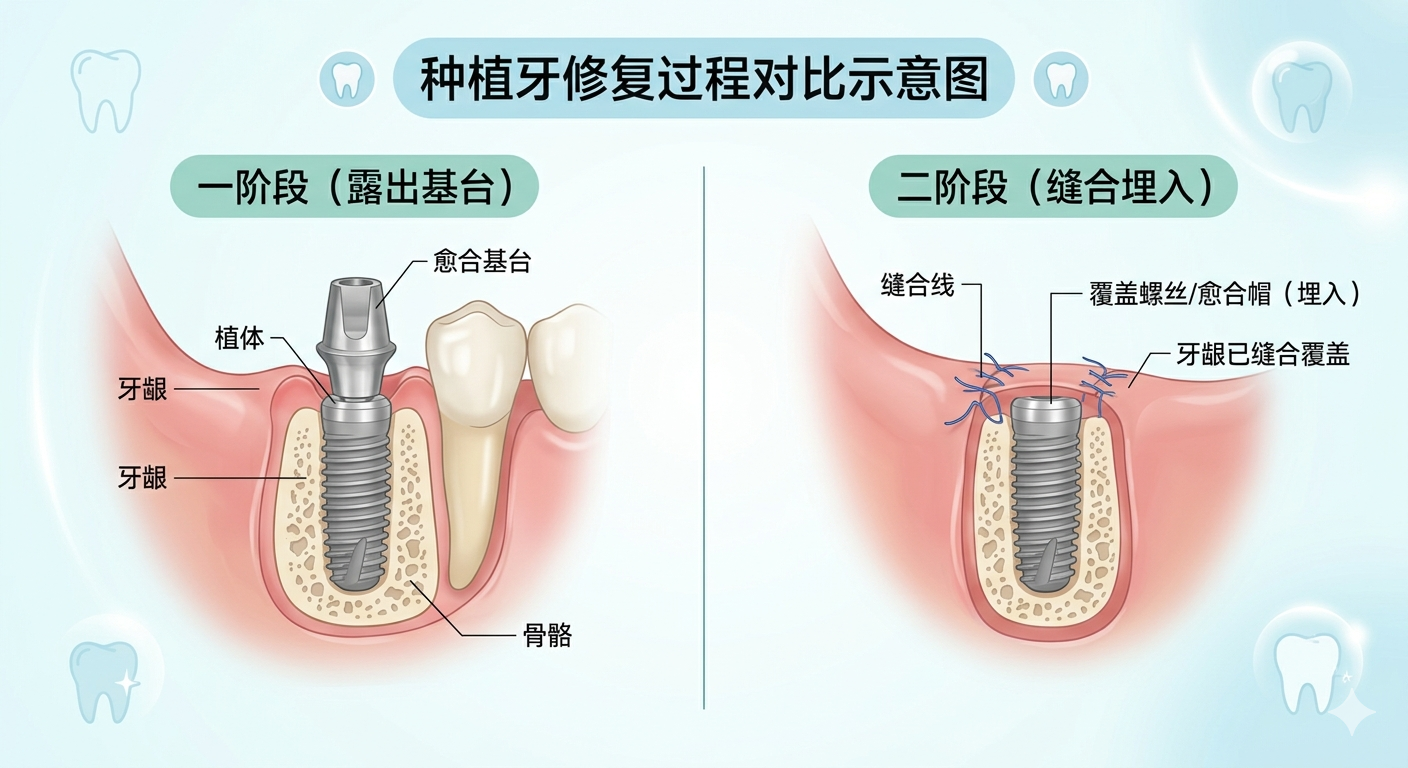
After the implant has been seated to the correct depth, the next step is to place the Healing Abutment.
Select a healing abutment of appropriate height and diameter. The healing abutment should be placed so that it extends 2.0mm above the gingival surface (supragingival exposure). This supragingival height facilitates soft tissue healing, maintains the transmucosal pathway, and allows for easy access during subsequent restorative procedures.
Finally, close the surgical site with interrupted or continuous sutures as dictated by the surgical flap design and tissue tension. The goal is to achieve tensionfree primary closure over the implant site while leaving the healing abutment exposed through the mucosa.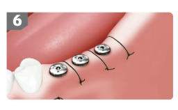
Key Technical Parameters at a Glance
Speed Settings by Instrument
Instrument Recommended Speed
Crest Remover (7.0mm) 1200–1500 RPM
Initial Positioning Drill 1200–1500 RPM
Bone Saw (7.0/10.0/13.0mm) 1200–1500 RPM
Expansion/Forming Drills 25–35 RPM
Torque and Irrigation Considerations
Maximum recommended torque for expansion drills: 35 Ncm
Manual expansion method: If resistance exceeds 35 Ncm, attach mount extension and complete expansion manually.
Irrigation: Copious external irrigation with sterile saline is recommended throughout all drilling steps to prevent thermal osteonecrosis.
Implant Selection Guide
Bone Density Recommended Implant Diameter
Standard bone 4.5mm
Hard/dense bone 4.0mm
Clinical Benefits of the ESSET Technique
Elimination of MalletRelated Patient Discomfort
The most immediate benefit appreciated by patients is the complete absence of mallet strikes. Conventional ridge splitting using chisels and mallets transmits significant mechanical impact forces to the skull, which many patients find distressing. Some patients experience postoperative dizziness or vertigo related to these impacts. The ESSET Kit’s motorized approach eliminates these concerns entirely.
H3: Reduced Risk of Buccal Plate Fracture
The expansion drills expand the split bone by selftapping, which minimizes the risk of buccal plate fracture. The sequential, gradual expansion allows the bone to deform within its elastic limits rather than fracturing abruptly. This safety feature is particularly valuable in the mandible, where dense cortical bone increases fracture risk.
Excellent Primary Stability for Immediate Loading
By harnessing the elasticity of the expanded bone, the ESSET technique achieves strong initial stability. The elastic recoil of the expanded bone generates circumferential compression around the conical implant body, producing insertion torque values that often support immediate loading protocols. The high implant survival rates reported for ridge split procedures—96.6% success and 96.8% survival with an average followup of 58.3 months—provide strong evidence for the longterm predictability of this approach.
Enhanced Healing Through FourWall Defect
The ESSET technique creates a fourwall bony defect around the implant. This configuration enhances blood supply from all sides simultaneously, promoting faster healing. The abundant blood supply brings osteoprogenitor cells and growth factors to the site, accelerating bone regeneration. In many cases, this eliminates the need for additional bone graft or membrane, reducing both treatment cost and morbidity.
Placement of 4.0mm and 4.5mm Implants in Previously Unacceptable Ridges
Perhaps the most significant clinical advantage of the ESSET Kit is its ability to place standarddiameter implants (4.0mm and 4.5mm) in narrow ridges that would otherwise preclude implant placement or require extensive grafting procedures. This expands treatment options for patients with anatomically restrictive scenarios and reduces the overall treatment burden.
Potential Complications and How to Avoid Them
Buccal Plate Fracture
Prevention: Always use the expansion drills in sequence, never skipping sizes. Maintain the recommended speed range (25–35 RPM) for expansion. If resistance is encountered, switch to manual expansion using the mount extension rather than forcing the handpiece.
Management: If a nondisplaced fracture occurs, continue with implant placement; the implant will stabilize the fractured segment. If a displaced or comminuted fracture occurs, consider aborting the ridge split approach and converting to GBR with membrane coverage.
Insufficient Primary Stability
Prevention: Ensure adequate ridge width (minimum 4.0mm) preoperatively. Complete the full sequential expansion with all four forming drills before implant placement. Select the appropriate implant diameter based on bone density.
Management: If primary stability is inadequate despite proper technique, consider using a largerdiameter implant, placing the implant deeper (subcrestal), or postponing loading to allow for osseointegration before prosthetic restoration.
Thermal Necrosis
Prevention: Use copious external irrigation throughout all drilling steps, particularly during sawing and expansion. Avoid prolonged, continuous drilling; use intermittent drilling motions to allow heat dissipation.
Management: If bone appears charred or emits a burnt odor during drilling, stop immediately, irrigate copiously, and allow the site to cool before proceeding.
PostOperative Care and FollowUp
Following the ESSET ridge split procedure, standard postimplant placement protocols apply. The patient should be prescribed appropriate analgesics and, if indicated, antibiotics. A soft diet is recommended for the first 7–10 days to minimize loading on the healing implants.
If immediate loading is planned, a provisional restoration should be placed out of occlusion. The definitive restoration can typically be placed after 3–4 months of healing, though this timeline may vary based on bone quality, implant stability values, and the clinician’s judgment.
Radiographic followup at 3–6 months postoperatively is recommended to confirm osseointegration and assess marginal bone levels.
Conclusion
The Osstem ESSET Kit represents a significant advancement in ridge split technology, offering a safe, predictable, and minimally invasive solution for placing dental implants in narrow alveolar ridges. By eliminating chisels and mallets, the technique enhances patient comfort while reducing the risk of buccal plate fracture. The sequential expansion protocol using tapered forming drills leverages the viscoelastic properties of bone to achieve excellent primary stability, often enabling immediate loading. The creation of a fourwall defect enhances blood supply and accelerates healing, potentially eliminating the need for additional grafting.
With an easytofollow surgical sequence, clear speed and torque parameters, and a proven clinical track record developed over a decade of refinement, the ESSET Kit empowers clinicians to treat narrow ridge cases with confidence, expanding treatment possibilities and improving patient outcomes.